STANDARD OPERATING PROCEDURE — EOD & DEMOLITION OPERATOR
1. PURPOSE & SCOPE
This SOP governs the employment of the EOD & Demolition Operator within Bronze Squadron using the EOD: Hand Entry system. It covers the operator's kit, the wire-cutter tool, the IED and trigger types found in the system, the procedure for defusing a device, and the complete rule set for cutting the correct wire and solving the switch-code puzzle.
All content herein describes in-game mechanics of the EOD: Hand Entry mod only. This is a training reference for a video-game system, not a real-world procedure.
2. THE EOD/DEMO OPERATOR BILLET
The EOD & Demolition Operator is a dedicated specialist within the team. The billet carries two responsibilities: neutralising enemy explosive threats, and emplacing friendly demolition charges. The operator is the element's answer to any IED on the objective and the element's tool for destroying enemy vehicles.
Responsibilities
- Defuses enemy IEDs found on the objective by inspecting the device, deducing the correct wire, and cutting it.
- Neutralises triggers linked to a device before the main charge is approached where possible.
- Emplaces vehicle charges against enemy vehicles for destruction or denial.
- Keeps the assault element clear of any device the operator is working, and calls the outcome once actioned.
3. OPERATOR KIT & LOAD
The EOD & Demolition Operator carries the following as standard. Nobody else on the element is expected to carry the defusal kit — it is the operator's to manage.
| Item | Purpose |
|---|---|
| Demo Charges × 2 | General-purpose demolition charges carried for destruction tasks on the objective. Two carried as standard. |
| Wire-Cutters Tool | The single tool used to cut wires on a device. See Section 4. |
| Vehicle Charges × 2–5 | Demolition charges carried for the destruction or denial of enemy vehicles. The operator carries between two and five per load. |
KIT STANDARD: 2× demo charges + wire-cutters + 2–5 vehicle charges.
Without the wire-cutters the operator cannot defuse a device. Confirm the full kit is loaded before load-in.
4. TOOLS — WIRE-CUTTERS
The wire-cutters are the operator's only defusal tool. Every device in the system is worked by cutting one of its four wires with this tool. The cut is final: cutting the correct wire defuses the device; cutting the wrong wire detonates it.
Employment
- Equip the wire-cutters when working a device.
- Inspect the device and read the four wires before selecting one. See Section 7.
- Cut only the wire the rule set directs. Do not test-cut — there is one cut, and it is the answer.
5. IED TYPES
The system presents four IED bodies. All are defused the same way — by reading the wires and applying the rule set — but the operator should recognise each on sight.
| IED | Description |
|---|---|
| IED Jug | A makeshift jug-bodied explosive device. Defused via the four-wire system. |
| IED Shell | A shell-bodied variant. Adds variety to a scenario but is defused by the same wire logic as the Jug. |
| Pipe Bomb | A pipe-bodied explosive device. Worked by the same four-wire system. |
| Briefcase Bomb | A briefcase-bodied device. Defused by the same wire logic as the other bodies. |
Body type does not change the wire logic. The assigned rule set — not the IED body — decides which wire is cut.
6. TRIGGER TYPES
A device may be linked to a remote trigger. Triggers are set in Game Master and linked to an IED (right-click the trigger in GM, then right-click the IED to link the two). Where a trigger is present, deal with it before working the main device.
| Trigger | Description |
|---|---|
| Trail Cam | A remote trigger that initiates the linked device. Neutralise before approaching the main charge. |
| Pressure Plate | A ground trigger that initiates contact. Identify and avoid, then disarm. |
| Crush Wire | A wire-run trigger that initiates when crossed. Locate the run and disarm. |
TRIGGERS — ANYONE CAN DISARM: Triggers can be disarmed by anyone — not only the EOD operator. This lets the element clear a trigger while the operator stays focused on the main device. Clear the trigger first; a live trigger can initiate the device before the operator ever reaches the wires.
7. DEFUSAL PROCEDURE
Every device is worked in the same four steps. The four wires — Red, Blue, Yellow, and Black — each carry a condition: frayed, loose, scorched, or good. Each device is governed by exactly one of the seventeen rule sets, and its wire conditions are set to match that rule. The operator reads the conditions, finds the rule they satisfy, and cuts as directed.
- Inspect: Approach the device and read the condition of all four wires.
- Deduce: Match the wire conditions to the one rule set they satisfy (Section 8).
- Action: Cut the wire that rule directs with the wire-cutters.
- Outcome: Correct wire → device defused and the area is secure. Wrong wire → device detonates.
ONE CUT — NO SECOND CHANCES: Read all four wires and confirm the rule before you cut. There is no test cut and no undo. The wire conditions exist to point at one rule — identify it, then act. If the read is unclear, call it before committing the element.
8. WIRE-CUT RULES
Each device follows exactly one of these seventeen rules. Read the wire conditions, find the rule whose conditions are met, and cut the wire in the Action column.
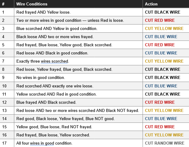
Rule 17 is a gamble — with all wires good, there is no safe wire to deduce, only a cut and a coin-flip. Treat any all-good device as high risk and clear the element back before cutting.
9. SWITCH-CODE PUZZLE
Some devices present a switch-code puzzle instead of wires. Inspect the device and read the three values shown — PVC, LOT, and REV. The final code is the remainder after dividing their sum by eight.
The Formula
FINAL CODE = ( PVC + LOT + REV ) ÷ 8, remainder
Add the three values, divide by 8, and use the REMAINDER as the final code (0–7).
Switch Values
Three switches each carry a value. Turn on the switches that add up to the final code, then press Confirm.

Code Reference
The remainder is always 0–7. Use this table to set the switches without doing the math twice.
| Final Code | Switches ON |
|---|---|
| 0 | None — leave all switches off, then Confirm. |
| 1 | A |
| 2 | B |
| 3 | A + B |
| 4 | C |
| 5 | A + C |
| 6 | B + C |
| 7 | A + B + C |
Worked Example
PVC 3 + LOT 4 + REV 6 = 13. 13 ÷ 8 leaves a remainder of 5. Code 5 = Switch A + Switch C. Turn on A and C, leave B off, then Confirm.
ZERO CASE: If the final code is 0, leave ALL switches off and press Confirm.